Komunikasi Serial Arduino
четверг 07 февраля admin 10
Now if you open your Arduino serial monitor at a baud rate of 9600, you’ll see a message appearing in your window saying “HI!” every 1 second. Schematics (3.3V FTDI Programmer), follow the next schematics to establish a serial communication between your FTDI programmer and your ESP8266 to upload some code. Downloading ESPlorer IDE I recommend using the ESPlorer IDE which is a program created by 4refr0nt to create and save Lua files into your ESP8266. Follow these instructions to download and install ESPlorer: • to download ESPlorer • Unzip that folder • Go to the main folder • Run ESPlorer.jar • Open the ESPlorer (as shown in the Figure below).
Writing Your ESP8266 Script Copy and paste the code below into ESPlorer IDE window.  -- Rui Santos -- Complete project details at ledOn = 0 pin=4 gpio.mode(pin,gpio.OUTPUT) uart.on('data', 3, function(data) print('Received from Arduino:', data) if data=='HI!'
Then if ledOn==0 then ledOn = 1 gpio.write(pin,gpio.HIGH) print('LED On') else ledOn = 0 gpio.write(pin,gpio.LOW) print('LED Off') end end end, 0). Summary: The ESP is configured to listen to serial communications. Every time that receives the string “HI!” at a baud rate of 9600, it will turn the GPIO 2 on or off. Uploading Your Script When you open the ESPlorer IDE you should see a window similar to the preceding Figure, follow these instructions to send commands to your ESP8266: • Connect your FTDI programmer to your computer • Set bad raute as 9600 • Select your FTDI programmer port (COM3, for example) • Press Open/Close • Select NodeMCU+MicroPtyhon tab • Copy the your Lua script into ESPlorer Then you simply click the button Save to ESP and save your file with the name “init.lua”. Everything that you need to worry about or change is highlighted in red box in the following Figure.
Sebelumnya telah dibahas apa itu Arduino. Nah sekarang kita mencoba kumunikasi serial Arduino untuk menampilkan tulisan 'HelloWorld' pada komputer. Untuk peralatan yang diperlukan cukup dengan Arduino Board saja. Langsung saja kita buat source code programnya untuk arduino. Tulis code berikut ini pada Arduino Software, kalau belum punya download dulu di sini.
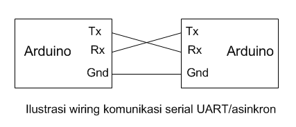
Final Circuit Follow the next schematics to complete this tutorial. Note: I’m using a voltage divider to shift the TX signal of the Arduino from 5V to 3.3V. This works well for slow baud rates, but it might not work at faster baud rates. For more information about lowering the voltage of signals.
Demonstration Now your LED should be blinking every one second. This means that your Arduino is sending the string “HI” and your ESP is receiving that data.
Watch the video at the beginning of this post for a live demonstration. Now instead of sending a string saying just “HI!”, you can attach sensors to your Arduino and send that data to your ESP instead. Later you can that displays that data. Read Next You might also find interesting trying one of these tutorials: • • • Do you have any questions? Leave a comment down below!
Thanks for reading. If you like this post probably you might like my next ones, so please support me by subscribing my.
44 thoughts on “ Raspberry Pi and Arduino Connected Over Serial GPIO” • Siva Sankar Hello, I used the same wiring method and the data exchange is good. However it is not reliable, when i run a ping pong data exchange simultaneously for thousands and millions of time in a loop, and at the same time performing some motor controls from arduino (Motors are known to draw current up to 0.8 A), the data is getting corrupted. The data corruption happens when the setup demands more current (for controlling motors).

Measures taken by me to solve this problem, > i have added shield to the wires Tx and Rx. > grounding is verified properly. Still i dont know how when the setup draws more current, the data on Tx and Rx is corrupted. Any help will be appreciated. ↓ • roger Hello, I have a similar situation. I’d like to connect an Arduino Uno to a 3.3v sensor through RX/TX Now I understand Arduino-TX -> sensor-RX needs a voltage divider ( so the 5V of the arduino doesn’t break the sensor). Now I’d expect the 3.3V from the sensor TX to Arduino-RX to be “safe”, however you mention in some situations the Arduino-RX can be at 5V, which would then go to the sensor and might break it So question ( assuming not using a level-divider) – why not have 2 voltage dividers?
( for both TX-RX and RX-TX connections) – could we put a schottky diode between the “Arduino-RX” to “sensor-TX”, to make sure there can only be a flow from the sensor to the Arduino, and and the diode blocks the other way around ( note: n00b here, so I might be completely misunderstanding it ). ↓ • Ralf S Hey Oscar!